Prosthetic valves may be made from metal and other material or may be biologic grafts (i.e., heterografts, homografts, or autografts). Mechanical grafts last longer than bioprostheses but require long-term anticoagulation. The potential advantage of the bioprostheses is that anticoagulation is required only early after placement unless indicated for other reasons, such as the presence of atrial fibrillation. Porcine heterografts are the most commonly used ones; they cannot be implanted in children, however, because of the relatively rapid calcification that occurs. Homografts (i.e., human valves) and autografts (i.e., grafts from the same individual—as in the placement of the pulmonary valve in the aortic position) may be less prone to calcification. The Ross procedure is a recently developed surgical approach in which the patient's pulmonary valve is placed in the aortic position and a homograft is placed in the pulmonary position. The lower pressure gradient across the homograft in the pulmonary position may make it less prone to calcification. An important role of transesophageal echocardiography is to measure the size of the annulus to be certain that appropriately sized homografts are available and, in the case of the Ross procedure, to be certain that the pulmonary valve is of the right size for placement in the aortic position.
The most commonly used mechanical valve is the St. Jude valve. Newer valves such as the Carbomedics (Sulzer Carbomedics Inc., Austin, TX) and Medtronic-Hall (Meditronics, Inc., Minneapolis, MN) valves are preferred by some surgeons, and their use is increasing. The echocardiographer must also be familiar with other valves, such as the Bjork-Shiley and Starr-Edwards valves, because large numbers of these implants are still functioning.
Problems that can occur with all valves include paravalvular leaks, infection, and thrombus. Bioprosthetic valves may also calcify and degenerate.
Because all mechanical and bioprosthetic valves are inherently a little stenotic, a region of flow acceleration can often be seen proximal to the valve during the flow across the valve. Because of the presence of localized areas of high-velocity flow, the Doppler study may overestimate the gradient across the prosthetic valve. The assessment of the prosthetic valve stenosis must therefore be approached with great caution, and published tables giving normal ranges for various prosthetic valves are not very helpful. The problem is further complicated by prosthesis–patient mismatch seen in some patients. Therefore, high-pressure gradients noted across prosthetic valves, especially metallic ones, do not necessarily imply obstruction. Because of this, measurement of prosthetic orifice areas using the Doppler continuity equation or pressure half-time method may not be accurate. A baseline study performed at the time of surgery can be helpful so that changes in pressure gradients can be followed up over time. It is important to investigate the motion of the occluder or leaflets when assessing stenosis. Immediately after the termination of cardiopulmonary bypass, the flow may be inadequate to open one of the leaflets of the mechanical prosthetic valve. This is a normal finding that resolves over time as cardiac output increases. For valves in the mitral position, a flat EF slope in association with a high velocity on conventional Doppler study suggests obstruction.
Valve prostheses may normally have a small amount of regurgitation. In the case of the St. Jude and CarboMedics valves, up to three small regurgitant jets are seen. These correspond to the two leaflets and to a central jet. Compared with pathologic regurgitant jets, these normal jets tend to be more laminar and narrow. In mitral prostheses the jets may, however, extend well into the left atrium. In assessing the severity of the prosthetic mitral regurgitation, it is important to investigate the pulmonary veins near their entry into the left atrium with the conventional Doppler to search for systolic backflow, which is a reliable marker for severe regurgitation. The size of the proximal flow acceleration should also be assessed. Finally, the area of the jet is important (<4 cm2, mild regurgitation; 4 to 8 cm2, moderate regurgitation; >8 cm2, severe regurgitation), although jet area may be misleading if an eccentric jet is present. Multiple planes should be interrogated to find the plane in which the regurgitant jet has the largest area. The Nyquist limit should be kept between 40 and 50 cm/sec. Changes in the Nyquist limit, and consequently the wall filter, will affect the jet area. The spontaneous contrast in the left atrium suggests that any mitral regurgitation is not severe. In the case of aortic prostheses, the aortic regurgitant jet may be seen best by the transthoracic approach because there is acoustic shadowing of the jet on the transesophageal examination, caused by the metallic components and posterior calcification. For prostheses in the aortic position, the severity of the regurgitation is assessed by determining the ratio of jet width at its origin to left ventricular outflow tract diameter, also measured at the origin of the jet (<38%, mild; 39% to 75%, moderate; >75%, severe).
Paravalvular leaks may be important causes of regurgitation. These leaks may be caused by valve suture dehiscence and can be seen to originate beyond the extent of the prosthetic elements. The location of proximal flow acceleration outside the confines of the prosthesis may also help determine if the leak is paravalvular.
Thrombi can lead to emboli or to obstruction or may interfere with the function of a valve and cause significant regurgitation. Thrombi may be present in the left atrium or left atrial appendage and may well be seen on the transesophageal study. Because the left atrial appendage may be partially or completely removed at the time of surgery, inability to image it should not be taken as evidence that there is a clot obscuring the appendage. Left ventricular function is better preserved if the papillary muscles are not completely removed; remnants of the papillary muscle and chordae left in place by the surgeon may be mistaken for a mobile clot. For this reason, a baseline transesophageal study is of great use for comparison.
Transesophageal and transthoracic examinations are complementary in patients with a mitral valve replacement. Transesophageal study is far more effective than is transthoracic examination in assessing the left atrium for the presence and severity of mitral regurgitation in patients with valves in the mitral position. On transthoracic study, acoustic shadowing of the left atrium by the valve is observed. Conversely, substantial acoustic shadowing and reverberation that degrade the transesophageal image of the left ventricle are present on transesophageal study but not on transthoracic examination.
Certain structures are well examined by transesophageal echocardiography. The short-axis view of a prosthetic valve permits a complete view of the valve suture line. Stents are well seen, and, in the case of mitral prostheses, may physically narrow the left ventricular outflow tract or may impinge on the left ventricular free wall or ventricular septum, producing arrhythmias or conduction system abnormalities. Bioprosthetic mitral cusp rupture resulting from degeneration or infection may be manifested as linear echoes protruding into the left atrium, with or without fluttering. Left atrial perforation or dissection may be seen. Abscesses may be visualized. They may be large and filled with pus. The presence of flow signals in the abscess cavity demonstrates that there is communication with an adjoining vessel or cavity. Abscesses may form fistulas to other structures. Following aortic valve replacement, systolic anterior motion of the mitral valve may be unmasked, and significant left ventricular outflow tract obstruction may develop in the presence of coexisting hypertrophic cardiomyopathy. Rarely, a left ventricular outflow tract gradient may be caused by an abscess narrowing the outflow tract. Pannus may cause obstruction and may be difficult to distinguish from clot. If the obstructing echo density is mobile and less dense thrombus is more likely. Bioprosthetic valves may suffer cusp degeneration or calcification, which may produce obstruction. Linear echoes protruding into the left ventricular outflow tract are characteristic of prolapse caused by bioprosthetic aortic valve degeneration. Similar echoes may also be caused by infection.
Transesophageal echocardiography is also useful in the assessment of mitral annuloplasty rings, which are placed to reduce the severity of mitral regurgitation. Residual mitral regurgitation, as well as ring thrombus, obstruction, and dehiscence, are well demonstrated. Systolic anterior motion of the anterior mitral leaflet with left ventricular outflow tract obstruction may also occur after ring placement and can be diagnosed by echocardiography. In patients undergoing aortic valvuloplasty, the site of aortic valve repair and the severity of residual aortic regurgitation are also well assessed by transesophageal echocardiography.
|
|
|
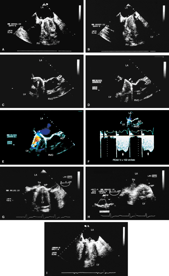
FIGURE 5.1. St. Jude mitral prosthesis: normal. The mitral prosthesis (MP) is seen in the closed (A) and open (B) positions. A. Prosthetic reverberations or artifacts (arrows) that clutter the left ventricle (LV). B. The two leaflets (1 and 2) of the prosthesis in the open position together with the reverberations. C. Aliased diastolic inflow into the LV is seen with a small region of flow acceleration. D–G. Two to three small jets of mitral regurgitation (MR; arrows) are shown. These are normal findings. Usually, these jets are narrow and do not show significant turbulence but may extend deep into the left atrium (LA). G. illustrates the norm (not pansystolic). H. Small linear echoes are normally seen on both the atrial and ventricular aspects of the prosthesis and represent suture material. I, J. Immediately postsurgery, although the patient is still on partial bypass, one leaflet of the prosthesis (P) may intermittently fail to open. This should not be mistaken for dysfunction. When cardiac output improves, normal opening of both leaflets occurs consistently. RV, right ventricle; RA, right atrium. |
|
|
|
FIGURE 5.2. St. Jude mitral prosthesis: thrombus. A–F. Localized echo densities consistent with thrombus (T) are noted on the St. Jude prosthesis (P) in two different patients (A,B and C–F). In both patients, thrombus prevented the opening of one of the leaflets of the prosthesis. F. Continuous wave Doppler shows a flat velocity profile in early diastole (arrows) and a high peak velocity of 152 cm/sec consistent with obstruction. G and H (one patient) and I (another patient) show two other patients with thrombosed (TH, T) St. Jude mitral prostheses. The echo densities representing thrombus are seen on the atrial side of the prosthesis. Thrombi are less dense than the metallic components of the prosthesis and are different from prosthetic reverberations, which are anteriorly directed, more prominent, and have larger linear echoes. In addition, reverberations are not seen on the atrial aspect of the prosthesis. AO, aorta; LA, left atrium; LV, left ventricle; MP, mitral prosthesis; RA, right atrium; RV, right ventricle; RVO, right ventricular outflow tract. |
|
|
|
FIGURE 5.3. St. Jude mitral prosthesis: paravalvular regurgitation. A. A large eccentric jet (arrowheads) coursing medially along the atrial septum is seen originating beyond the edges of the prosthetic elements (P). B. The paraprosthetic leak (arrowheads) is located laterally. There is also a large zone of flow acceleration (FA), which is clearly located outside the confines of the prosthetic valve (P). C. The dehisced area (arrow) is clearly seen, and a wide jet of paravalvular regurgitation (oblique arrow) can be seen coursing through it (D). The vertical arrows point to two small jets of normal valvular regurgitation through the St. Jude prosthesis. E,F. Another patient with dehiscence of sutures and pansystolic paravalvular regurgitation. G,H. Another patient with suture dehiscence (arrow in G) and severe eccentric MR (arrowheads), with a large FA on the ventricular aspect of the St. Jude prosthesis. I. There is eccentric periprosthetic MR (white arrows) as well as eccentric TR (yellow arrows) moving along the atrial septum. Two small normal jets of MR also are seen originating from the St. Jude prosthesis. LA, left atrium; LV, left ventricle; MP, mitral prosthesis; RA, right atrium; RV, right ventricle;RVO, right ventricular outflow tract. |
|
|
|
FIGURE 5.4. A,B. St. Jude mitral prosthesis: ectopic position. In this patient, the St. Jude prosthesis (P) is attached to the wall of the left atrium (LA) (upper arrowhead in B) rather than to the valve ring (lower arrowheads). LV, left ventricle; RA, right atrium; RV, right ventricle. |
|
|
|
FIGURE 5.5. CarboMedics mitral prosthesis: normal. A–C. Schematics of the CarboMedics mitral prosthesis. In A, the CarboMedics aortic prosthesis is also shown. C. The mechanism of normally occurring MR through the hinge points (courtesy of Sulzer CarboMedics Inc., Austin, TX). D. The prosthesis is seen in the four-chamber view, demonstrating multiple reverberations (1, 2, 3, 4) partially obscuring the left ventricle (LV) and right ventricle (RV) cavities. E. Both leaflets of the prosthesis and the suture ring (arrow) are viewed in the short axis. F. Individual sutures (arrowheads) are seen on the atrial aspect of the prosthetic valve. G. Diastolic flow acceleration (arrowhead) on the atrial aspect of the prosthesis. The LV inflow jet is large. H,I. Two small jets of normal prosthetic valvular regurgitation (arrowheads). R, prosthetic reverberations. AO, aorta; AV, aortic valve; LA, left atrium; LAA, left atrial appendage; MPA, main pulmonary artery; PA, pulmonary artery; RA, right atrium; VS, ventricular septum. |
|
|
|
FIGURE 5.6. A–E. CarboMedics mitral prosthesis: dehiscence of left atrium (LA) wall. A. A small linear echo (vertical arrow) at the site of the paravalvular defect (horizontal arrow) consistent with suture material. B. Color Doppler examination shows a large paravalvular regurgitant jet originating at the site of the paravalvular defect (arrow) shown in A. C. An abnormal 1-cm linear echo (arrow) protrudes into the LA at the midinteratrial septal level. D,E. Multiplane views at 105° and 111° demonstrate a cavitary defect (arrows) involving the LA wall at the midinteratrial septal level, indicative of dehiscence, which explains the presence of the linear echo in the LA seen in C. F–H. CarboMedics mitral prosthesis (MP): LA pseudoaneurysm. F. A large pseudoaneurysm (AN; arrow) that developed following prosthetic replacement (MP, arrowhead) of the mitral valve.G,H. Color Doppler examination shows flow signals (arrowhead in H) moving from the left ventricle (LV) into the aneurysm cavity. AO, aorta; RA, right atrium; RMVP, reverberations from mitral valve prosthesis. (A–E reproduced with permission from Howard J, Agrawal G, Nanda NC. Transesophageal echocardiographic diagnosis of left atrial wall dehiscence. Echocardiography 1997;14:299–302. ) |
|
FIGURE 5.7. Bjork-Shiley mitral prosthesis: thrombus/pannus. A. A small echo density consistent with thrombus (T) is seen within the ring of the prosthesis (P). B. Its presence is confirmed by the flat diastolic velocity profile (arrows) and a high peak pressure gradient (16 mm Hg) across the prosthesis, consistent with obstruction. C–K. Another patient with a thrombosed Bjork-Shiley mitral prosthesis. Note the spontaneous contrast (SC) echoes in the left atrium (LA) in C, G, and J. I. A thrombus (TH) is well seen on the atrial aspect of the prosthesis (PMV) imaged with a probe in the esophagus, whereas the thrombus on the ventricular aspect is best visualized during transgastric examination (I).Another thrombus (TH) is present in the left atrial appendage (LAA) (G). Color Doppler–directed continuous wave Doppler reveals a very flat diastolic velocity profile with a very high peak velocity of 305 cm/sec, indicative of very severe flow obstruction. K. The arrowhead in J shows prominent flow acceleration on the atrial aspect of the prosthesis. R, prosthetic ring. L. Another patient with a Bjork-Shiley prosthesis. In this patient, the echo density on the ventricular aspect of the prosthesis (P) was found at surgery to be a pannus (PAN) rather than a thrombus. Spontaneous echo contrast (SEC) was present in LA. M. Gross specimen of a thrombosed mitral prosthetic valve. AO, aorta; LV, left ventricle; RV, right ventricle, spontaneous contrast. |
|
|
|
FIGURE 5.8. Bjork-Shiley mitral prosthesis: suture dehiscence. The arrow in A shows a large area of dehiscence with severe paraprosthetic (P) MR (arrow in B). LA, left atrium; LV, left ventricle; RA, right atrium; RV, right ventricle. |
|
|
|
FIGURE 5.9. Cooley-Cutter mitral prosthesis: stenosis. A. Prosthetic reverberations (arrow). B. A questionable thrombus (arrow). C,D. Prominent flow acceleration (FA) is present on the atrial aspect of the prosthesis (MP, P). E. A high velocity of 176 cm/sec was measured across the prosthesis by continuous wave Doppler (arrows). F. Associated mild mitral regurgitation (MR). AO, aorta; LA, left atrium; LAA, left atrial appendage; LUPV, left upper pulmonary vein; LV, left ventricle; MP, mitral prosthesis; MR, mitral regurgitation; RVO, right ventricular outflow tract. |
|
|
|
FIGURE 5.10. Starr-Edwards prosthesis: normal. A. The rounded poppet (arrows) is seen in the open position in diastole and in the closed position in systole. B. Transgastric view shows the three prosthetic struts (arrows) together with the resulting reverberations imaged in short axis. C. Gross specimen shows Starr-Edwards prostheses in the aortic and mitral positions. LA, left atrium; LV, left ventricle. |
|
|
|
FIGURE 5.11. Starr-Edwards mitral prosthesis: dehiscence. The poppet, or ball (B), is seen in the closed (A) and open (B) positions. Note the reverberations from the ball partially obscuring the left ventricle (LV) in B. C,D. Eccentric, severe paravalvular mitral regurgitation (arrowheads) originating beyond the prosthetic (P) elements is shown. E.Color M-mode examination demonstrates systolic backflow (arrowheads) in the left upper pulmonary vein (LUPV), confirming the presence of severe MR. C, C, mitral ring. F. Gross specimen shows suture dehiscence and clot involving a Starr-Edwards prosthesis. AO, aorta; LA, left atrium; RA, right atrium; RV, right ventricle. |
|
|
|
FIGURE 5.12. Mitral annuloplasty rings. A. R points to the Carpentier ring in the mitral position. There is no obstruction to mitral flow. B. Gross specimen of Carpentier ring.C,D. Duran ring in the mitral position (arrows in C). D. Color Doppler examination shows prominent flow acceleration and aliased flow resulting from narrowing of the mitral orifice by the ring. AO, aorta; LA, left atrium; LV, left ventricle; RVO, RVOT, right ventricular outflow tract. |
|
|
|
FIGURE 5.13. Mitral annuloplasty ring. A. R demonstrates an annuloplasty ring in the mitral position. S, sutures. B. Color Doppler examination shows aliased inflow signals and prominent diastolic flow acceleration (arrow) produced by narrowing of the mitral orifice by the ring. C. Pulsed-Doppler examination of the left upper pulmonary vein (PV) shows a smaller S wave than D wave, consistent with moderate mitral regurgitation (MR) preoperatively. After ring placement, the S wave is equal to the D wave, suggesting a reduction in mitral regurgitation (in D). E. Another patient in whom the annulus size was reduced to 2.64 cm after placement of an annuloplasty ring for severe MR. LA, left atrium; LV, left ventricle, RV, right ventricle. |
|
|
|
FIGURE 5.14. Mitral annuloplasty ring. The ring (R) is seen in diastole in A and in systole in B. C. Color Doppler examination shows moderate residual mitral regurgitation (MR) in this patient, who had severe MR before ring placement. D. A systolic frame shows ring (R) echoes in another patient following mitral annuloplasty. LA, left atrium; LV, left ventricle; MV, mitral valve; PA, pulmonary artery; RV, right ventricle; RVO, right ventricular outflow tract. |
|
|
|
FIGURE 5.15. Mitral annuloplasty ring: ruptured chordae. A. Ruptured chordae (arrowheads) prolapsing into the left atrium (LA) in systole. R, mitral annuloplasty ring. B,C.Color Doppler examination demonstrates severe eccentric mitral regurgitation (MR) (arrowheads) through the ring with prominent systolic backflow (SBF) in the LUPV (D). AO, aorta; LAA, left atrial appendage; LUPV, left upper pulmonary vein; LV, left ventricle; MV, mitral valve; RA, right atrium; RV, right ventricle. |
|
|
|
FIGURE 5.16. Mitral annuloplasty ring: obstruction. A,B. Prominent diastolic flow acceleration (arrow) and a narrow inflow jet resulted from obstruction produced by a Duran ring in this patient. LA, left atrium; LV, left ventricle; MV, mitral valve; RA, right atrium; RV, right ventricle. |
|
|
|
FIGURE 5.17. Mitral annuloplasty ring: thrombus/dehiscence. A. A thrombus (arrow) involving the ventricular aspect of a Duran ring. There is severe mitral valve (MV) prolapse. B–D. Another patient with a flail Duran ring (R) and thrombus formation (arrow in D). In B the flail ring is shown in systole in the left atrium. C. Another systolic frame, showing the ring now prolapsing into the ventricle. In this patient, the Duran ring had dehisced and was attached only by a single remaining suture. AO, aorta; LA, left atrium;LV, left ventricle; RA, right atrium, RV, right ventricle. (Reproduced with permission from Osman K, Willman B, Nanda NC, et al. Transesophageal echocardiographic findings of a dehisced duran mitral annuloplasty ring. Echocardiography 1995;12:441–446. ) |
|
|
|
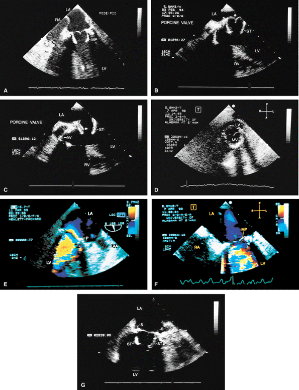
FIGURE 5.18. Porcine mitral prosthesis: normal. The porcine prosthesis is shown in the closed position (A, B; arrow in B) in systole and in the open position (arrow in C) in diastole. D. The porcine prosthesis imaged in short axis. E. Mitral prosthetic (P) inflow with a localized area of flow acceleration on the atrial side of the valve. F. A systolic frame demonstrates absence of regurgitation through the prosthesis mitral prosthesis (MP). G. ST, prosthetic stents in left ventricle (LV); S, sutures on the atrial side. AV, aortic valve; LA, left atrium; MV, mitral valve; LAA, left atrial appendage; RA, right atrium; RV, right ventricle. |
|
|
|
FIGURE 5.19. Porcine mitral prosthesis: stenosis and regurgitation. A. A large diastolic flow acceleration (arrowheads) on the atrial side of the prosthesis (P), suggesting the presence of obstruction. B. Thickening and calcification of the prosthesis resulting from degeneration. C. A decreased slope of the diastolic velocity profile with a measured mitral valve area (MVA) of 0.9 cm2 measured by the pressure half-time technique, indicating significant obstruction. D. Associated severe valvular mitral regurgitation (MR) (arrowheads). Images B through D are from the same patient. AO, aorta; LA, left atrium; LV, left ventricle; PA, pulmonary artery; RA, right atrium; RV, right ventricle; RVO, right ventricular outflow tract. |
|
|
|
FIGURE 5.20. Porcine mitral prosthesis: spontaneous contrast and thrombus in the left atrium (LA). A. M-mode study shows spontaneous contrast (arrows). B,C. A large thrombus (TH) in the left atrial appendage (LAA). The prosthetic leaflets are only mildly thickened (B). D. Extensive thrombus formation (TH) in the left atrium in another patient with an obstructed porcine mitral prosthesis. AO, aorta; LV, left ventricle; MVP, mitral valve prosthesis; RA, right atrium; RVO, right ventricular outflow tract. (Creproduced with permission from Mahan EF III, Nanda NC. Transesophageal echocardiography. In: Rackley CE, ed. Challenges in Cardiology I. Mt. Kisco, NY: Futura, 1991:85–101. ) |
|
|
|
FIGURE 5.21. Porcine mitral prosthesis: paravalvular regurgitation. A. A laterally located area of prosthetic (MP) dehiscence (arrow). B–D. An eccentric jet of mitral regurgitation (MR) (arrowheads) originating in the area of prosthetic (P) dehiscence. E. Color M-mode demonstrates systolic backflow (arrows) in the left upper pulmonary vein (LUPV), indicative of severe MR. After repair, the dehisced area is no longer seen (F), and there is absence of systolic backflow in LUPV (G). AS, atrial septum; FA, flow acceleration; LA, left atrium; LV, left ventricle; RA, right atrium; RV, right ventricle. |
|
|
|
FIGURE 5.22. Porcine mitral prosthesis: paravalvular and valvular regurgitation. A. Thickened prosthetic (P) leaflets (arrowhead) and a large area of lateral dehiscence (arrow). B. Valvular and paravalvular mitral regurgitation (MR) (arrowheads). C. Prominent systolic backflow (arrows) is noted in the left upper pulmonary vein (LUPV). D–F.Another patient with thickened prosthetic (MVR) leaflets, prominent diastolic flow acceleration, and lateral paravalvular regurgitation (arrows). The MR jet is narrow as a result of the Coanda effect, caused by the jet impinging against the left atrium (LA) lateral wall. Systolic backflow was present in the LUPV, however, indicative of severe MR. This was confirmed by angiography. LV, left ventricle; RVO, right ventricular outflow tract; RA, right atrium. |
|
|
|
FIGURE 5.23. Mitral prosthesis: valvular regurgitation. A–C. S represents the valve stents, and the arrow in B points to a suture. Color Doppler examination demonstrates three jets of mitral regurgitation (MR) (E) associated with two areas (arrows) of prominent flow acceleration on the ventricular side of the prosthesis in D. F. Systolic backflow in left atrial appendage (LAA) indicates severe MR. Although MR was pansystolic in this patient, the systolic backflow occurred only in mid- and late systole, because it takes some time for the MR jet to travel to LAA from the prosthesis. G. Postoperative study shows absence of severe MR and two jets (arrows) of mild, normal mitral prosthetic (MP) regurgitation. LA, left atrium; LUPV, left upper pulmonary vein; LV, left ventricle. |
|
|
|
FIGURE 5.24. Porcine mitral prosthesis: degeneration. A. Heavily calcified mitral prosthetic (MP) leaflets (arrow). S, prosthetic stents (shown in A and B). C,D. The calcified leaflets (arrows) and the prosthetic ring (R) are viewed in short axis. LA, left atrium; LV, left ventricle; RV, right ventricle. |
|
FIGURE 5.25. Porcine mitral prosthesis: cusp rupture. A. Marked bowing (arrow) of the prosthetic (P) leaflets into the left atrium caused by prolapse. There is no evidence of cusp rupture. B–F. Rupture of the cusps (arrowheads) is seen. Note prominent linear protrusion of the ruptured leaflets into the left atrium (LA). F. Coarse systolic flutter of a ruptured cusp (arrowhead). G. Torrential mitral regurgitation (MR), together with a large area of flow acceleration (FA), on the ventricular aspect of the prosthesis. B and C are from one patient; D–G are from another patient. H,I. Another patient with porcine cusp prolapse and rupture (arrowhead in H), with severe MR (arrowheads) and prominent FA in I. J–L. Rupture of thickened porcine mitral cusps (arrowheads in J,K) with severe, eccentric MR (arrowheads in L) through the prosthesis (P). M. Another patient with porcine (P) cusp rupture with severe MR (arrows) shown in both color two-dimensional and M-mode images (arrows). N. The arrow points to severe valvular MR from cusp rupture; arrowheads show associated severe paravalvular MR. O,P. Gross specimens show porcine prosthetic cusp rupture. LA, left atrium; RA, right atrium; LV, left ventricle; RV, right ventricle; LVOT, left ventricular outflow tract; RVO, right ventricular outflow tract. |
|
|
|
FIGURE 5.26. Porcine mitral prosthesis: left atrial pseudoaneurysm. Apical two-chamber view (longitudinal plane examination). A. A narrow, 2-mm wide channel (arrow) is seen extending from the left atrium (LA) into a 1.3-cm pseudoaneurysm cavity (circled). B. A diastolic frame shows color-flow signals moving from the pseudoaneurysm into the left atrium during diastole (arrow). C. Pulsed-Doppler examination shows to-and-fro motion of blood flow signals, which move into the pseudoaneurysm during systole and out of it into LA during diastole. MP, mitral prosthesis; LV, left ventricle. (Reproduced with permission from Ballal R, Nanda NC, Sanyal R. Intraoperative transesophageal echocardiographic diagnosis of left atrial pseudoaneurysm. Am Heart J 1992;123:217–218. ) |
|
|
|
FIGURE 5.27. Porcine mitral prosthesis: regurgitation. A. Color Doppler–guided pulsed Doppler interrogation of left upper pulmonary vein (LUPV) demonstrates prominent systolic backflow (arrow), indicative of severe mitral regurgitation (MR). Because LUPV is dilated, there is systolic swirling of blood flow, with forward flow (red) seen medially and backflow (blue) more laterally. Color guidance is important for placing the pulsed Doppler sample volume in the blue and not in the red flow signals to demonstrate systolic backflow diagnostic of severe MR. B. Reduced S wave (arrows) suggests moderate MR in another patient. There is no systolic backflow. LV, left ventricle; LA, left atrium. |
|
|
|
FIGURE 5.28. St. Jude aortic prosthesis: normal. A. Prosthetic aortic valve (PAV) leaflets (arrowhead) and suture ring (arrow), imaged in short axis. B. R marks the suture ring, also imaged in short axis but without the leaflets. C,D. M-mode tracings demonstrate normal motion of the prosthesis aortic valve (AV). E. An arc-like prosthetic side lobe artifact (R). G is the intraluminal tube graft in the aorta (AO). DIAS, diastole; LA, left atrium; RA, right atrium; PA, pulmonary artery; RVO, right ventricular outflow tract; RV, right ventricle; SYS, systole. |
|
|
|
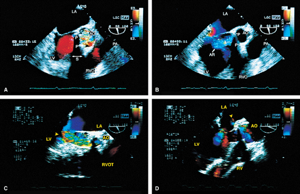
FIGURE 5.29. A–E. St. Jude aortic prosthesis: paravalvular leak. A. Prosthetic (P) ring dehiscence (arrow). B,E. Color-flow Doppler demonstrates paravalvular aortic regurgitation (AR) (arrows) moving through the dehisced area into the left ventricular outflow tract (LVOT). C. A large flow acceleration (FA) and significant AR. AO, aorta; LA, left atrium; LV, left ventricle; PA, pulmonary artery; RV, right ventricle; RA, right atrium; RVO, right ventricular outflow tract; VS, ventricular septum. |
|
|
|
FIGURE 5.30. CarboMedics aortic prosthesis: normal. A. The prosthesis in the closed position in diastole (arrowhead). B. Both leaflets in the open position (arrow) in systole.C. The leaflets (arrowhead) are open in systole. The suture ring is also seen in C and in D and E (arrow). F,G. Two jets of normal mild aortic regurgitation (AR) (arrows) that are eccentrically located. LA, left atrium; AO, aorta; LV, left ventricle; RVOT, right ventricular outflow tract. |
|
|
|
FIGURE 5.31. CarboMedics aortic prosthesis: paravalvular regurgitation. A,B. The aortic regurgitation (AR) jet occupies essentially the entire left ventricular outflow tract (LVOT) proximally, indicative of severe regurgitation. In both A and B, the most proximal portion of the AR jet is not imaged because of acoustic shadowing (S) caused by the metallic prosthesis (P), calcification, or both. AO, aorta; RPA, right pulmonary artery; RVO, right ventricular outflow tract. |
|
|
|
FIGURE 5.32. Bjork-Shiley aortic prosthesis: thrombus/dehiscence/abscess. A,B. A large thrombus (T) involving the aortic prosthesis (P). C. Another patient with a thrombus on the aortic prosthesis (AP) and severe associated aortic regurgitation (AR). Diastolic mitral regurgitation (MR) caused by severe AR is also noted. D. Paravalvular AR caused by dehiscence of prosthetic (P) sutures (arrow). Note the presence of two arc-like side lobe artifacts (R). E–H. A large abscess (A) involving the prosthesis (P) posteriorly together with severe AR (arrowheads in G). I–K. Another patient with an abscess cavity (AB) located on the posterior aspect of the prosthesis (PAV) and communicating with the left ventricular outflow tract (LVOT) (K). L. A patient with an infected Bjork-Shiley prosthesis with associated perforation at the base of the anterior mitral leaflet. The arrowheads demonstrate the MR jet moving through the perforation. The large flow acceleration (FA) suggests the presence of severe MR, although the jet through the perforation appears small. Note a second tiny MR jet arising from the coaptation point. AO, aorta; LA, left atrium; LAA, left atrial appendage; LVO, left ventricular outflow tract; LV, left ventricle;MV, mitral valve; RA, right atrium; RV, right ventricle; RVO, right ventricular outflow tract. (Reproduced with permission from Mahan EF III, Nanda NC. Transesophageal echocardiography. In: Rackley CE, ed. Challenges in Cardiology I. Mt. Kisco, NY: Futura, 1991:85–101. ) |
|
|
|
FIGURE 5.33. Starr-Edwards aortic prosthesis: normal. The arrows in A and C point to the three struts of the prosthesis. LM, left main coronary artery. B. Labels 1 and 2 point to reverberations from the strut that partially obscure the right ventricle (RV). B–D. The acoustic shadowing produced by the poppet (ball, B) is well seen (arrow in D). E. Gross specimen of a normal Starr-Edwards prosthesis in the aortic position. AO, aorta; LA, left atrium; LV, left ventricle; PA, pulmonary artery; RA, right atrium; RVO, right ventricular outflow tract; RV, right ventricle. |
|
|
|
FIGURE 5.34. Starr-Edwards prosthesis: paravalvular regurgitation. A. Note the presence of acoustic shadowing (S) in the systolic frame. B. An eccentric jet of paravalvular prosthetic (P) aortic regurgitation (AR). C. Another patient with severe paravalvular AR (arrowhead) from a Starr-Edwards prosthesis that was placed 32 years earlier. D.Following replacement with another mechanical prosthesis a small fistulous communication is noted into the left atrium (LA) (arrowhead). AO, aorta; LV, left ventricle; PA, pulmonary artery; RVO, RVOT, right ventricular outflow tract. |
|
|
|
FIGURE 5.35. Medtronic-Hall prosthesis: abscess/paravalvular leak. A. A large abscess cavity (A) is noted in the area of the prosthesis. R, a prominent reverberation artifact.B. Eccentric paravalvular aortic regurgitation (AR) (arrow), with prominent flow acceleration on the aortic side of the valve. C. Severe AR (arrowheads) with some proximal acoustic shadowing is noted. D–G. Another patient with multiple abscesses (A) involving the prosthesis (P). An abscess (A) encroaches on the anterior mitral leaflet (E). G. Color Doppler examination shows flow signals within the abscess cavity, indicating communication with the aorta (AO) or left ventricle (LV). This patient underwent homograft replacement of the infected Medtronic-Hall prosthesis. H. A small hematoma (H) is noted posterior to the prosthesis (P) in the postoperative study. LA, left atrium; RA, right atrium; RV, right ventricle; RPA, right pulmonary artery; RVO, right ventricular outflow tract; VS, ventricular septum. |
|
|
|
FIGURE 5.36. Medtronic-Hall prosthesis: abscess/aortopulmonary fistula. A–E. The modified four-chamber and five-chamber views demonstrate a portion of the aortic prosthesis (arrow) protruding into the left ventricular outflow tract (LVOT). The anterior leaflet of the mitral valve (MV) shows two perforations, one at the base (1) and the other in the midportion (2). Mitral regurgitation (MR) jets are seen moving into the left atrium (LA) through these perforations (MR-1, MR-2) and also from the coaptation area of the mitral leaflets (MR-3). B. The diastolic frame shows the prosthesis in contact with the body of the anterior mitral leaflet (AML) in the area of the perforation. E. Both valvular (V) and paravalvular (P) aortic regurgitation (AR) are noted. F,G. Modified aortic short-axis views demonstrate the fistulous connection between the aortic root (A) and the main pulmonary artery (PA) through an abscess cavity (A3). Two other abscess cavities (A1, A2) are also noted. H,I. Abscess cavity A2 is well demonstrated. J,K. The relationship of the abscess cavity A1 to the superior vena cava (SVC) during transverse (J) and longitudinal (K) plane examinations is demonstrated. L–N. Longitudinal plane examination shows the abscess cavity A3. Its communication with the PA is seen in N. AO, aorta; LV, left ventricle; PML, posterior mitral leaflet; RA, right atrium; RV, right ventricle; RVO, right ventricular outflow tract; SVC, superior vena cava. (Reproduced with permission from Chen CH, Nanda NC, Fan PH, et al. Transesophageal echocardiographic diagnosis of aortopulmonary fistula. Echocardiography 1993;10:85–90. ) |
|
|
|
FIGURE 5.37. A–H. Porcine aortic prosthesis: normal. The leaflets (A, arrowheads in C–E and G, arrow in F) and the stents (ST, arrows in E and G) of the prosthesis (P) are well seen. Because the metallic stents are highly echogenic, they may obscure the thin leaflets. It may be necessary to use multiple transducer angulations to see the leaflets as completely as possible. F. M-mode tracing of the prosthesis (AP) shows it in the open and closed position (arrows). H. Gross specimen of a normal porcine prosthesis in the aortic position. AO, aorta; LA, left atrium; LV, left ventricle; RV, right ventricle; RVO, right ventricular outflow tract. |
|
FIGURE 5.38. Porcine aortic prosthesis: degeneration/prolapse/valvular regurgitation. A. A thickened, stenotic prosthesis (P) with marked restriction of the opening (arrowhead) in systole. B–E. Another patient with thickened prosthetic leaflets (arrows in B,C) prolapsing into the left ventricular outflow tract (LVOT). D. The proximal portion of the aortic regurgitation (AR) jet (arrows) is not imaged because of acoustic shadowing produced by the calcified prosthesis. E. Severe AR (arrow) is seen in this patient. F.Another patient with very mild thickening and degeneration of the porcine prosthesis (PAV). G. More severe thickening and degeneration of the prosthesis (P) than that seen inF. H,I. Another patient with a degenerated PAV. The arrow in H points to a linear echo protruding from the prosthesis in diastole. This finding is common in the setting of degeneration. J–L. A different patient with a heavily calcified prosthesis (P) that prolapses into the LVOT (arrows). Associated severe AR is shown in L. M,N. Linear echoes (arrows) that prolapse into the LVOT in a patient with a thickened, degenerated heterograft prosthesis (P). O. Prolapse (arrowhead) of a heterograft prosthesis (P) in a patient who has an aortic (AO) aneurysm. P. Mild thickening and degeneration of a heterograft prosthesis (P) in another patient with aortic root aneurysm and dissection. F, dissection flap; FL, false lumen. Q,R. Gross specimens with calcification and thickening on the ventricular (Q) and aortic (R) aspects of a heterograft prosthesis. LA, left atrium; LV, left ventricle; MV, mitral valve; PA, pulmonary artery; RA, right atrium; RV, right ventricle; RVO, right ventricular outflow tract. |
|
|
|
FIGURE 5.39. Porcine aortic prosthesis: valvular and paravalvular regurgitation. A. Prolapse (arrowhead) of a thickened and degenerated prosthesis (P). B–D. Aortic regurgitation (AR) flow signals are shown moving into the left ventricular outflow tract (LVOT) posteriorly from beyond the confines of the prosthesis, indicative of a paravalvular leak. C. Associated valvular regurgitation originating from within the confines of the aortic prosthesis. An anterior paraprosthetic leak is also demonstrated (white arrow). The black arrows in B and C show the site of the posterior paravalvular leak. E. Another patient with heterograft prosthesis (P) cusp prolapse demonstrating severe AR.LA, left atrium; LV, left ventricle; PA, pulmonary artery; RA, right atrium, RV, right ventricle; RVO, right ventricular outflow tract. |
|
|
|
FIGURE 5.40. Porcine aortic prosthesis: cusp rupture. The arrowheads in A and B show a ruptured cusp prolapsing into the left ventricular outflow tract (LVOT), with severe aortic regurgitation (AR) shown in C through E (arrowheads in D, arrows in E). Diastolic mitral regurgitation (MR) (arrowheads) from severe AR is noted in C. F is a gross specimen of a thickened and calcified porcine aortic valve with cusp rupture (circled). AO, aorta; LA, left atrium; LV, left ventricle; P, prosthesis; RA, right atrium; RV, right ventricle. |
|
|
|
FIGURE 5.41. Porcine aortic prosthesis: tear of right coronary cusp. The arrowhead in A shows a torn right coronary cusp of the porcine prosthesis (P) prolapsing into the left ventricular outflow tract (LVOT) with severe aortic regurgitation (AR) (B). LA, left atrium; LV, left ventricle; RA, right atrium; RV, right ventricle. |
|
|
|
FIGURE 5.42. Porcine aortic prosthesis: paravalvular regurgitation. A. The arrow points to a mildly thickened porcine aortic valve (PAV). B. Eccentric paravalvular aortic regurgitation (AR) (arrow) originating in the vicinity of the posterior prosthetic stent (S). There is no valvular regurgitation. AO, aorta; LA, left atrium; LV, left ventricle; MV, mitral valve; RV, right ventricle. |
|
|
|
FIGURE 5.43. Porcine aortic prosthesis: abscess/fistula. A,B. A large abscess cavity is noted posteriorly communicating with the left ventricular outflow tract (LVOT). AP, aortic prosthesis; P, prosthesis. C–I. Another patient with a large abscess cavity (A, AB, arrow in G) located on the posterior aspect of the prosthesis (P, AP). H,I. Color Doppler studies in the same patient show the abscess cavity communicating with the LVOT in diastole (H) and systole (I). J–L. Another patient with a heterograft who has a rounded abscess cavity, best seen in K (arrow), protruding into the left atrium (LA) and close to the aortic–mitral junction. J. The prosthetic leaflets (closed arrow) and the stents (open arrows) do not appear to be abnormally thick. L. Color Doppler examination shows the presence of significant aortic regurgitation (AR). M,N. Another patient with an infected porcine prosthesis showing a fistula into the right ventricle (RV) (arrows). AO, aorta; LV, left ventricle; MR, mitral regurgitation; MV, mitral valve; RA, right atrium; RVO, right ventricular outflow tract. |
|
|
|
FIGURE 5.44. Ionescu-Shiley porcine prosthesis: prolapse/abscess/regurgitation. The arrow in A shows prolapse of a cusp into the left ventricular outflow tract (LVOT) with associated severe prosthetic (P) aortic regurgitation (AR) (B). This patient was found to have cusp rupture at surgery. C–H. Another patient with the same type of prosthetic (P) valve showing prolapse and abscess formation. The arrowhead in C shows cusp prolapse into the LVOT. An abscess (A) cavity is seen on the posterior and lateral aspects of the prosthesis (C,D). E,F. Color Doppler examination shows the abscess cavity (arrow in F) communicating with the LVOT. G,H. Diastolic mitral regurgitation (MR) (arrowheads) resulting from severe AR (arrows) is seen. AO, aorta; LA, left atrium; LV, left ventricle; PA, pulmonary artery; RA, right atrium; RVO, right ventricular outflow tract; RV, right ventricle. |
|
|
|
FIGURE 5.45. Porcine aortic prosthesis: hypertrophic cardiomyopathy. In this patient, systolic anterior motion (SAM) of the mitral valve developed after porcine aortic valve replacement for aortic stenosis, which had masked coexisting hypertrophic cardiomyopathy. Note that the left ventricular outflow tract (LVOT) is narrowed to <20 mm in this patient. AO, aorta; AP, aortic prosthesis; LA, left atrium; LV, left ventricle. |
|
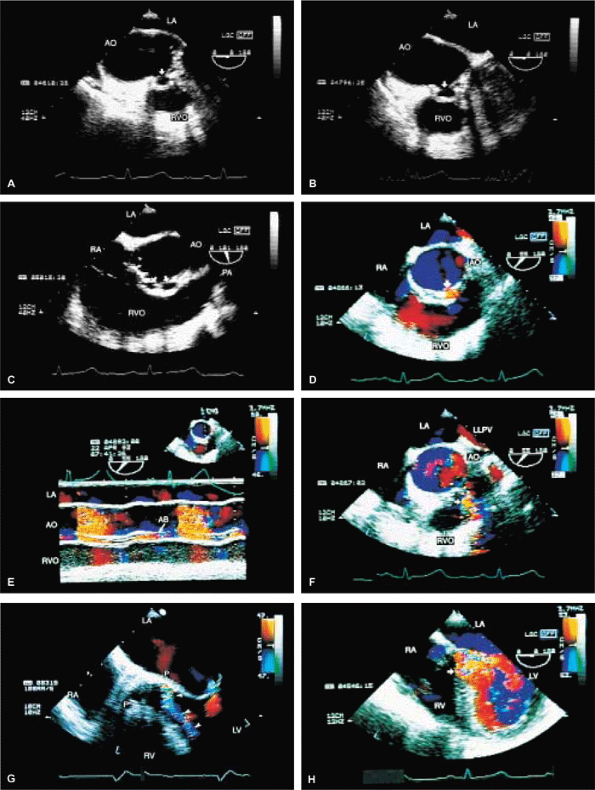
FIGURE 5.46. Homograft aortic prosthesis: degeneration/stenosis/prolapse/regurgitation/infection. A. Thickening and calcification of the prothesis (P) with marked restriction of opening during systole is indicative of stenosis. B. Color Doppler shows a very narrow jet (arrowheads) originating from the prosthesis in systole, also indicative of obstruction. C–F. Another patient with prosthetic (P) cusp prolapse (arrow in C), with severe eccentric aortic regurgitation (AR) and prominent flow acceleration (FA in D,E) on the aortic side. The AR jet is directed posteriorly and abuts against the anterior mitral leaflet. This valve was replaced with a St. Jude prosthesis (P)(F). Labels 1 and 2 indicate normal small prosthetic AR jets. Jet 1 originates anteriorly but is directed posteriorly (red). Conversely, jet 2 originates posteriorly but is directed anteriorly (blue). H, a small hematoma. G,H. Another patient with prosthetic (P) cusp prolapse (arrow) resulting in diastolic noncoaptation with the right coronary leaflet and producing severe AR (H). I. A patient with homograft prosthetic degeneration and severe AR (arrowheads). J. Color Doppler study of another patient with a homograft aortic prosthesis (P) showing severe AR (arrows). Note that the jet shows largely laminar flow with only a small amount of turbulence (variance) because of the nonperpendicular orientation of the ultrasonic beam relative to the direction of blood flow. K–N. A patient with homograft endocarditis. K. Marked diastolic prolapse (arrows) of the thickened prosthetic leaflets (P) with noncoaptation. A large vegetation (V) is seen prolapsing into the left ventricular outflow tract (LVOT) in diastole in L and into the aortic root in systole in M. N. Color Doppler examination shows severe AR and minimal pulmonary regurgitation (PR). O–V. Another patient with endocarditis involving a homograft prosthesis (P). The arrows in O, P, and Rshow prosthetic dehiscence and a large pseudoaneurysm posteriorly. Q–V. A fistula (F, arrows) from the aortic root into the RV and an abscess cavity (AB in S and T) are seen. V.Color Doppler–guided continuous wave Doppler shows flow through the fistula throughout the cardiac cycle. AB, abscess; AO, aorta; LA, left atrium; LVO, left ventricular outflow tract; LV, left ventricle; MV, mitral valve; PA, pulmonary artery; RA, right atrium; RVO, right ventricular outflow tract; RV, right ventricle. |
|
|
|
FIGURE 5.47. Homograft aortic prosthesis: endocarditis. A–C. Abscess cavities (arrows) communicating with the aortic root. The prosthetic leaflets are thickened. D,E. Color Doppler examination demonstrates flow signals (arrow in D) in the abscess (AB) cavity. F. Fistula (arrow) from the aorta (AO) to the right ventricle (RV). G,H. Severe aortic regurgitation (AR) (arrows) is demonstrated. LA, left atrium; LLPV, left lower pulmonary vein; LV, left ventricle; PA, pulmonary artery; RA, right atrium; RVO, right ventricular outflow tract. |
|
|
|
FIGURE 5.48. Homograft aortic prosthesis: subaortic obstruction produced by abscess. Longitudinal (A) and transverse (B) plane examinations showed abscess cavity (arrows) and narrowing of left ventricular outflow tract (LVOT) more clearly than did a transthoracic study. The abscess cavity communicates with LVOT posteriorly; anteriorly, it appears closed. Homograft aortic valve (AV) leaflets are only mildly thickened. C. Left panel. a systolic frame shows aliasing and narrowing of the flow channel in LVOT, indicative of subaortic obstruction (longitudinal plane examination). Right panel. a diastolic frame shows color Doppler flow signals occupying <25% of the proximal LVOT, consistent with mild aortic regurgitation (AR) (transverse plane examination). AO, aorta; LA, left atrium; LV, left ventricle; LVO, left ventricular outflow tract; MV, mitral valve;RVO, right ventricular outflow tract. (Reproduced with permission from Sanyal RS, Roychoudhury D, Nanda NC, et al. Transthoracic and transesophageal echocardiographic diagnosis of severe subaortic obstruction produced by an abscess cavity. Am Heart J 1994;128:1252–1255. ) |
|
|
|
FIGURE 5.49. Pulmonary autograft in the aortic position with homograft replacement of the pulmonary valve (PV) (Ross operation): prolapse/valvular and paravalvular regurgitation. A. Prolapse (arrowhead) of the prosthesis (P) placed in the aortic position. B,C. Severe posteriorly directed eccentric regurgitation (arrows). D–F. Another patient with prolapse of the autograft. The arrow in D shows noncoaptation caused by severe prolapse of the noncoronary cusp (NCC). Resulting severe aortic regurgitation (AR) (arrow) with prominent flow acceleration is seen in E. The arrow in F points to redundancy and noncoaptation of the prosthetic leaflets viewed in short axis. G. Another patient with an autograft who has a hole (upper arrow) in the right coronary cusp. The homograft pulmonary valve (lower arrow) in this patient is mildly thickened. H. Another patient with a pulmonary autograft in the aortic position with suture dehiscence and a posterior paravalvular leak. AO, aorta; LA, left atrium; LV, left ventricle; RA, right atrium; RV, right ventricle; RVOT, right ventricular outflow tract; VS, ventricular septum. |
|
|
|
FIGURE 5.50. Aortic valve annuloplasty. This patient presented with severe prolapse and noncoaptation (arrow in A) of the aortic valve leaflets, resulting in severe aortic regurgitation (AR) (arrowheads in B). Following aortic valve annuloplasty, AR is reduced and now is only mild (arrow in C). AO, aorta; LA, left atrium; LV, left ventricle; PA, pulmonary artery; RVOT, right ventricular outflow tract. |
|
|
|
FIGURE 5.51. Tricuspid valve prosthesis and ring. A. A pannus (arrow) involving a metallic tricuspid prosthesis valve (TVP). B. Mild tricuspid regurgitation (TR) (arrow) in the same patient. S, acoustic shadowing caused by the prosthesis. C. Turbulent inflow into the right ventricle (RV) (arrow) is seen in the diastolic frame. This metallic prosthesis was replaced by a CarboMedics prosthesis. D,E. Another patient with a normal porcine tricuspid prosthesis (P). F. A Carpentier annuloplasty ring (R) in the tricuspid position in another patient. AO, aorta; LA, left atrium; LV, left ventricle; MV, mitral valve; RA, right atrium. |
|
|
|
FIGURE 5.52. Pulmonary valve prosthesis. A prosthesis (PP) is shown in the pulmonary position in this patient, who also had repair of a ventricular septal defect (arrows inA,E). B. Turbulent flow (arrow) in the pulmonary artery (PA) in systole. The peak velocity by continuous wave Doppler measured 2.48 m/sec (C), which is within normal limits for a prosthetic valve. D. Associated severe pulmonary regurgitation (PR) is shown. E. This patient also had moderate aortic regurgitation (AR). AO, aorta; AV, aortic valve; LA, left atrium; LM, left main coronary artery; LV, left ventricle; RVO, right ventricular outflow tract. |
Suggested Readings
Alam M, Rosman HS, Sun I. Transesophageal echocardiographic evaluation of St. Jude medical and bioprosthetic valve endocarditis. Am Heart J 1992;123:236–239.
Andrade A, Vargas-Baron J, Romero-Cardenas A, et al. Transthoracic and transesophageal echocardiographic study of pulmonary autograft valve in aortic position. Echocardiography 1994;11:221–226.
Azari DM, DiNardo JA. The role of transesophageal echocardiography during the Ross procedure. J Cardiothorac Vasc Anesth 1995;9:558–561.
Ballal R, Nanda NC, Sanyal R. Intraoperative transesophageal echocardiographic diagnosis of left atrial pseudoaneurysm. Am Heart J 1992;123:217–218.
Botero M, Fuchs R, Paulus DA, et al. Carcinoid heart disease: a case report and literature review. J Clin Anesth 2002;14:57–63.
Cape EG, Nanda NC, Yoganathan AP. Quantification of regurgitant flow through bileaflet heart valve prostheses: theoretical and in vitro studies. Ultrasound Med Biol 1993;19:461–468.
Chen CH, Nanda NC, Fan PH, et al. Transesophagealechocardiographic diagnosis of aortopulmonary fistula. Echocardiography 1993;10:85–90.
Daniel LB, Grigg LE, Weisel RD, et al. Comparison of transthoracic and transesophageal assessment of prosthetic valve dysfunction. Echocardiography 1990;7:83–95.
Faletra F, De Chiara F, Corno R, et al. Additional diagnostic value of multiplane echocardiography over biplane imaging in assessment of mitral prosthetic valves. Heart 1996;75:609–613.
Flachskampf FA, Hoffmann R, Franke A, et al. Does multiplane transesophageal echocardiography improve the assessment of prosthetic valve regurgitation? J Am Soc Echocardiogr 1995;8:70–78.
Freedberg RS, Goodkin GM, Perez JL, et al. Valve strands are strongly associated with systemic embolization: a transesophageal echocardiographic study. J Am Coll Cardiol 1995;26:1709–1712.
Freeman WK, Schaff HV, Khandheria BK, et al. Intraoperative evaluation of mitral valve regurgitation and repair by transesophageal echocardiography: incidence and significance of systolic anterior motion. J Am Coll Cardiol 1992;20:599–609.
Garcia MJ, Vandervoort P, Stewart WJ, et al. Mechanisms of hemolysis with mitral prosthetic regurgitation. Study using transesophageal echocardiography and fluid dynamic simulation. J Am Coll Cardiol 1996;27:399–406.
Garcia-Fernandez MA, Perez-David E, Quiles J, et al. Role of left atrial appendage obliteration in stroke reduction in patients with mitral valve prosthesis: a transesophageal echocardiographic study. J Am Coll Cardiol 2003;42:1253–1258.
Hixson CS, Smith MD, Mattson MD, et al. Comparison of transesophageal color flow Doppler imaging of normal mitral regurgitant jets in St. Jude Medical and Medtronic Hall cardiac prostheses. J Am Soc Echocardiogr 1992;5:57–62.
Howard J, Agrawal G, Nanda NC. Transesophageal echocardiographic diagnosis of left atrial wall dehiscence. Echocardiography 1997;14:299–302.
Jaggers J, Chetham PM, Kinnard TL, et al. Intraoperative prosthetic valve dysfunction: detection by transesophageal echocardiography. Ann Thorac Surg 1995;59:755–757.
Jebara VA, Mihaileanu S, Acar C, et al. Left ventricular outflow tract obstruction after mitral valve repair. Results of the sliding leaflet technique. Circulation 1993;88:1130–1134.
Keser N, Nanda NC, Miller AP, et al. Hemodynamic evaluation of normally functioning Sulzer Carbomedics prosthetic valves. Ultrasound Med Biol 2003;29:649–657.
Khandheria BK. Transesophageal echocardiography in the evaluation of prosthetic valves. Am J Card Imaging 1995;9:106–114.
Khandheria BK, Seward JB, Oh JK, et al. Value and limitations of transesophageal echocardiography in assessment of mitral valve prostheses. Circulation 1991;83:1956–1968.
Labbe L, Roudaut R, Lorient-Roudaut MF, et al. Relationship between intra vascular hemolysis and bright sparkling echoes detected by TEE in the vicinity of mechanical mitral prosthesis. Echocardiography 1996;13:381–386.
Lange HW, Olson JD, Pederson WR, et al. Transesophageal color Doppler echocardiography of the normal St. Jude medical mitral valve prosthesis. Am Heart J 1991;122:489–494.
Lee TM, Chou NK, Su SF, et al. Left atrial spontaneous echo contrast in asymptomatic patients with a mechanical valve prosthesis. Ann Thorac Surg 1996;62:1790–1795.
Lerakis S, Robert Taylor W, Lynch M, et al. The role of transesophageal echocardiography in the diagnosis and management of patients with aortic perivalvular abscesses. Am J Med Sci 2001;321:152–155.
Mahan EF III, Nanda NC. Transesophageal echocardiography. In: Rackley CE, ed. Challenges in cardiology I. Mt. Kisco, NY: Futura, 1991:85–101.
Mohr-Kahaly S, Kupferwasser I, Erbel R, et al. Regurgitant flow in apparently normal valve prostheses: improved detection and semiquantitative analysis by transesophageal two-dimensional color-coded Doppler echocardiography. J Am Soc Echocardiogr 1990;3:187–195.
Nagueh SF, Bozkurt B, Li GA, et al. Progressive dehiscence and dynamic compression of an aortic root homograft—detection and characterization by transesophageal echocardiography. Am Heart J 1996;132:1070–1073.
Nellessen U, Schnittger I, Appleton CP, et al. Transesophageal two-dimensional echocardiography and color Doppler flow velocity mapping in the evaluation of cardiac valve prostheses. Circulation 1988;78:848–855.
Orsinelli DA, Pasierski TJ, Pearson AC. Spontaneously appearing micro-bubbles associated with prosthetic cardiac valves detected by transesophageal echocardiography. Am Heart J 1994;128:990–996.
Orsinelli DA, Pearson AC. Detection of prosthetic valve strands by transesophageal echocardiography: clinical significance in patients with suspected cardiac source of embolism. J Am Coll Cardiol 1995;26:1713–1718.
Osman K, Willman B, Nanda NC, et al. Transesophageal echocardiographic findings of a dehisced Duran mitral annuloplasty ring. Echocardiography 1995;12:441–446.
Pederson WR, Walker M, Olson JD, et al. Value of transesophageal echocardiography as an adjunct to transthoracic echocardiography in evaluation of native and prosthetic valve endocarditis. Chest 1991;100:351–360.
Robert F, Roudaut R, Pepin C, et al. Significance of “strands” on mitral mechanical prostheses during late follow-up after surgery. Echocardiography 1996;13:265–270.
Sanyal RS, Roychoudhury D, Nanda NC, et al. Transthoracic and transesophageal echocardiographic diagnosis of severe subaortic obstruction produced by an abscess cavity. Am Heart J 1994;128:1252–1255.
Shapira Y, Vaturi M, Weisenberg DE, et al. Impact of intraoperative transesophageal echocardiography in patients undergoing valve replacement. Ann Thorac Surg 2004;78:579–583; discussion 583–584.
Stoddard MF, Dawkins PR, Longaker RA. Mobile strands are frequently attached to the St. Jude medical mitral valve prosthesis as assessed by two-dimensional transesophageal echocardiography. Am Heart J 1992;124:671–674.
Taams MA, Gussenhoven EJ, Cahalan MK, et al. Transesophageal Doppler color flow imaging in the detection of native and Bjork-Shiley mitral valve regurgitation. J Am Coll Cardiol 1989;13:95–99.
van den Brink RBA, Visser CA, Basart DCG, et al. Comparison of transthoracic and transesophageal color Doppler flow imaging in patients with mechanical prostheses in the mitral valve position. Am J Cardiol 1989;63:1471–1474.
Vered Z, Mossinson D, Pelege E, et al. Echocardiographic assessment of prosthetic valve endocarditis. Eur Heart J 1995; 16(Suppl B):63–67.
Weinert L, Karp R, Vignon P, et al. Feasibility of aortic diameter measurement by multiplane transesophageal echocardiography for preoperative selection and preparation of homograft aortic valves. J Thorac Cardiovasc Surg 1996;112:954–961.